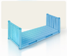
20′ TANK

Description


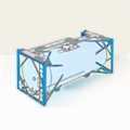
Tank containers must be at least 80%% full, to prevent dangerous surging of the liquids in transit. On the other hand, they must not as a rule be over 95%% full, or there will not be sufficient ullage space for thermal expansion. The extent of thermal expansion may be calculated for each cargo on the basis of the following formula:

  • ΔV = Va · γ · ΔT
  • Ve = Va (1 + γ · ΔT)

ΔV : change in volume
Va : volume at initial temperature a
Ve : final volume at temperature e
γ : coefficient of cubic (thermal) expansion
ΔT : temperature difference in degrees kelvin

Tank containers intended for transporting foodstuffs must be labeled “Potable Liquids only”.

Some hazardous materials must be transported in tank containers with no in- or outlet openings below the surface of the liquid.

Tank containers are generally designed for an operating pressure of up to 3 bar (above atmospheric). The test pressure used is 4.5 bar (above atmospheric).

If the cargo requires temperature-controlled transport, tank containers can be equipped with insulation or heating. The temperature of the cargo may be precisely controlled using temperature sensors.

Usage

Tank containers are used for liquid cargoes, such as:

  • Foodstuffs: fruit juices, spirits, sweet oils
  • Chemicals: hazardous materials, such as fuels, toxic substances, corrosion protection agents

SPECIFICATIONS


  • INSIDE LENGTH: 6.058 m
  • INSIDE WIDTH: 2.438 m
  • INSIDE HEIGHT: 2.438 m
  • DOOR WIDTH: 0.000 m
  • DOOR HEIGHT: 0.000 m
  • CAPACITY: 0 m3
  • TARE WEIGHT: 4190 Kgs
  • MAX CARGO WEIGHT: 26290 Kgs

20′ BULK

Description


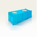
Bulk (or bulk cargo) containers have three loading hatches in the roof, each of a diameter of approx. 455 mm (1 3/4′). The distance between the hatches (center to center) is 1.83 m (6′). On the door side, there are two discharge hatches, which are sometimes equipped with short discharge tubes for guiding the bulk cargo. Alternatively, two unloading hatches may be mounted in the doorways, for emptying the containers.

Such containers may also be used for general cargo. Lashing rings are mounted in the top side rails for securing the cargo. Some bulk containers are equipped with forklift pockets, which allow handling by forklift trucks.

Usage

Bulk containers are used in particular for transporting bulk cargo, such as grain, feedstuffs, spices. However, they may also be used for transporting general cargo.

SPECIFICATIONS


  • INSIDE LENGTH: 5.934 m
  • INSIDE WIDTH: 2.358 m
  • INSIDE HEIGHT: 2.340 m
  • DOOR WIDTH: 2.335 m
  • DOOR HEIGHT: 2.292 m
  • CAPACITY: 32 m3
  • TARE WEIGHT: 2450 Kgs
  • MAX CARGO WEIGHT: 21550 Kgs

40′ REFRIGERATED

Description


The refrigeration unit is arranged in such a way that the external dimensions of the container meet ISO standards and thus fit into the container ship cell guides, for example. The presence of an integral refrigeration unit entails a loss of internal volume and payload.

When being transported by ship, integral units have to be connected to the on-board power supply system. The number of refrigerated containers which may be connected depends on the capacity of the ship’s power supply system. If the aforesaid capacity is too low for the refrigerated containers to be transported, “power packs” may be used, which are equipped with relatively large diesel generators and satisfy ISO requirements with regard to the dimensions of a 20′ container. When at the terminal, the containers are connected to the terminal’s power supply system. For transport by road and rail, most integral unit refrigeration units are operated by a generator set (genset). This may either be a component of the refrigeration unit or connected to the refrigeration unit.

Air flows through the container from bottom to top. In general, the “warm” air is drawn off from the inside of the container, cooled in the refrigeration unit and then blown back in the container as cold air.

To ensure adequate circulation of the cold air, the floor is provided with gratings. Pallets form an additional space between container floor and cargo, so also forming a satisfactory air flow channel. In addition, the side walls of the container are “corrugated”, which ensures satisfactory air flow there too.

In the upper area of the container, adequate space (at least 12 cm) must likewise be provided for air flow. For this purpose, during packing of the container adequate free space must be left above the cargo. The maximum load height is marked on the side walls.

To ensure vertical air flow from bottom to top, packaging must also be appropriately designed and the cargo must be sensibly stowed.

In addition to temperature regulation, integral units also allow a controlled fresh air exchange, for example for the removal of metabolic products such as CO2 and ethylene in the case of the transport of fruits.

In the refrigeration units, both the supply and return air temperatures are measured and, depending on the operating mode, one of these values is used to control the cold air. Temperature measurement may be performed in various ways. The Partlow recorder generally records return air temperature, since this provides an indication of the state or temperature of the cargo. Data loggers are increasingly used, which detect temperature digitally and indicate it on a display. Once transferred to a PC, the data may then be evaluated.

The temperature display is attached to the outside of the refrigeration unit, so that operation of the unit may be checked at any time.

Digital or analog recorders may also be positioned directly in the cargo, so as to measure temperatures inside the container. The recorder should be accommodated in such a way that it records the temperatures at risk points in the container (inside the packaging, top layer at door end).

Integral units may be stowed both above and below deck on a ship. Above deck stowage has the advantage that the heat from return air may be more readily dissipated. However, the containers are often exposed to strong solar radiation, leading to increased refrigeration capacity requirements.

Usage

Refrigerated containers are used for goods which need to be transported at a constant temperature above or below freezing point. These goods are divided into chilled goods and frozen goods, depending on the specified transport temperature. They principally include fruit, vegetables, meat and dairy products, such as butter and cheese.

High-cube integral units are used in particular for voluminous and light goods (e.g. fruit, flowers).

Nowadays, goods requiring refrigeration are mostly transported in integral units, which have a markedly higher market share than porthole containers.

Chilled meat is sometimes also transported hanging, for which purpose the ceilings of refrigerated containers are equipped with special hook rails

SPECIFICATIONS


  • INSIDE LENGTH: 11.840 m
  • INSIDE WIDTH: 2.286 m
  • INSIDE HEIGHT: 2.120 m
  • DOOR WIDTH: 2.286 m
  • DOOR HEIGHT: 2.195 m
  • CAPACITY: 60 m3
  • TARE WEIGHT: 3850 Kgs
  • MAX CARGO WEIGHT: 26630 Kgs

20′ REFRIGERATED

Description


The refrigeration unit is arranged in such a way that the external dimensions of the container meet ISO standards and thus fit into the container ship cell guides, for example. The presence of an integral refrigeration unit entails a loss of internal volume and payload.

When being transported by ship, integral units have to be connected to the on-board power supply system. The number of refrigerated containers which may be connected depends on the capacity of the ship’s power supply system. If the aforesaid capacity is too low for the refrigerated containers to be transported, “power packs” may be used, which are equipped with relatively large diesel generators and satisfy ISO requirements with regard to the dimensions of a 20′ container. When at the terminal, the containers are connected to the terminal’s power supply system. For transport by road and rail, most integral unit refrigeration units are operated by a generator set (genset). This may either be a component of the refrigeration unit or connected to the refrigeration unit.

Air flows through the container from bottom to top. In general, the “warm” air is drawn off from the inside of the container, cooled in the refrigeration unit and then blown back in the container as cold air.

To ensure adequate circulation of the cold air, the floor is provided with gratings. Pallets form an additional space between container floor and cargo, so also forming a satisfactory air flow channel. In addition, the side walls of the container are “corrugated”, which ensures satisfactory air flow there too.

In the upper area of the container, adequate space (at least 12 cm) must likewise be provided for air flow. For this purpose, during packing of the container adequate free space must be left above the cargo. The maximum load height is marked on the side walls.

To ensure vertical air flow from bottom to top, packaging must also be appropriately designed and the cargo must be sensibly stowed.

In addition to temperature regulation, integral units also allow a controlled fresh air exchange, for example for the removal of metabolic products such as CO2 and ethylene in the case of the transport of fruits.

In the refrigeration units, both the supply and return air temperatures are measured and, depending on the operating mode, one of these values is used to control the cold air. Temperature measurement may be performed in various ways. The Partlow recorder generally records return air temperature, since this provides an indication of the state or temperature of the cargo. Data loggers are increasingly used, which detect temperature digitally and indicate it on a display. Once transferred to a PC, the data may then be evaluated.

The temperature display is attached to the outside of the refrigeration unit, so that operation of the unit may be checked at any time.

Digital or analog recorders may also be positioned directly in the cargo, so as to measure temperatures inside the container. The recorder should be accommodated in such a way that it records the temperatures at risk points in the container (inside the packaging, top layer at door end).

Integral units may be stowed both above and below deck on a ship. Above deck stowage has the advantage that the heat from return air may be more readily dissipated. However, the containers are often exposed to strong solar radiation, leading to increased refrigeration capacity requirements.

Usage

Refrigerated containers are used for goods which need to be transported at a constant temperature above or below freezing point. These goods are divided into chilled goods and frozen goods, depending on the specified transport temperature. They principally include fruit, vegetables, meat and dairy products, such as butter and cheese.

High-cube integral units are used in particular for voluminous and light goods (e.g. fruit, flowers).

Nowadays, goods requiring refrigeration are mostly transported in integral units, which have a markedly higher market share than porthole containers.

Chilled meat is sometimes also transported hanging, for which purpose the ceilings of refrigerated containers are equipped with special hook rails

SPECIFICATIONS


  • INSIDE LENGTH: 5.724 m
  • INSIDE WIDTH: 2.286 m
  • INSIDE HEIGHT: 2.014 m
  • DOOR WIDTH: 2.286 m
  • DOOR HEIGHT: 2.067 m
  • CAPACITY: 26 m3
  • TARE WEIGHT: 2550 Kgs
  • MAX CARGO WEIGHT: 21450 Kgs

40′ PLATFORM

Description


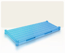
Platforms consist solely of a floor structure with extremely high loading capacity; they have no side or end walls. This high loading capacity makes it possible to concentrate heavy weights on small areas. A platform consists of a steel frame and a wooden floor structure.

Platforms are available in 20′ and 40′ sizes. 40′ platforms have a gooseneck tunnel at each end.

Lashing rings, to which the cargo may be secured, are installed in the side rails. The lashing rings may take loads of up to 3.000 kg.

SPECIFICATIONS


  • INSIDE LENGTH: 12.192 m
  • INSIDE WIDTH: 2.245 m
  • INSIDE HEIGHT: 0.648 m
  • DOOR WIDTH: 0.000 m
  • DOOR HEIGHT: 0.000 m
  • CAPACITY: 0 m3
  • TARE WEIGHT: 5700 Kgs
  • MAX CARGO WEIGHT: 39300 Kgs

20′ PLATFORM

Description


Platforms consist solely of a floor structure with extremely high loading capacity; they have no side or end walls. This high loading capacity makes it possible to concentrate heavy weights on small areas. A platform consists of a steel frame and a wooden floor structure.

Platforms are available in 20′ and 40′ sizes. 40′ platforms have a gooseneck tunnel at each end.

Lashing rings, to which the cargo may be secured, are installed in the side rails. The lashing rings may take loads of up to 3.000 kg.

SPECIFICATIONS


  • INSIDE LENGTH: 6.058 m
  • INSIDE WIDTH: 2.438 m
  • INSIDE HEIGHT: 0.370 m
  • DOOR WIDTH: 0.000 m
  • DOOR HEIGHT: 0.000 m
  • CAPACITY: 0 m3
  • TARE WEIGHT: 2520 Kgs
  • MAX CARGO WEIGHT: 27960 Kgs

40′ FLATRACK COLLAPSIBLE

Description


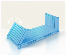
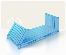
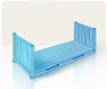
Flatracks consist of a floor structure with a high loading capacity composed of a steel frame and a softwood floor and two end walls, which may either be fixed or collapsible. The end walls are stable enough to allow cargo securing means to be attached and several flatracks to be stacked on top of one another. Flatracks are available in 20′ and 40′ sizes.

A number of lashing rings, to which the cargo may be secured, are installed in the side rails, the corner posts and the floor. The lashing rings may take loads of up to 2000 kg in the case of 20′ flatracks or up to 4000 kg in the case of 40′ flatracks.

Some types of 20′ flatracks have forklift pockets.

40′ flatracks have gooseneck tunnels at each end. In addition, they are sometimes equipped with lashing winches with 2 metric ton lashing belts.

For transport of certain cargoes, flatracks may be provided with stanchions.

SPECIFICATIONS


  • INSIDE LENGTH: 11.660 m
  • INSIDE WIDTH: 2.200 m
  • INSIDE HEIGHT: 2.245 m
  • DOOR WIDTH: 0.000 m
  • DOOR HEIGHT: 0.000 m
  • CAPACITY: 0 m3
  • TARE WEIGHT: 5700 Kgs
  • MAX CARGO WEIGHT: 39300 Kgs

20′ FLATRACK COLLAPSIBLE

Description


Flatracks consist of a floor structure with a high loading capacity composed of a steel frame and a softwood floor and two end walls, which may either be fixed or collapsible. The end walls are stable enough to allow cargo securing means to be attached and several flatracks to be stacked on top of one another. Flatracks are available in 20′ and 40′ sizes.

A number of lashing rings, to which the cargo may be secured, are installed in the side rails, the corner posts and the floor. The lashing rings may take loads of up to 2000 kg in the case of 20′ flatracks or up to 4000 kg in the case of 40′ flatracks.

Some types of 20′ flatracks have forklift pockets.

40′ flatracks have gooseneck tunnels at each end. In addition, they are sometimes equipped with lashing winches with 2 metric ton lashing belts.

For transport of certain cargoes, flatracks may be provided with stanchions.

SPECIFICATIONS


  • INSIDE LENGTH: 5.675 m
  • INSIDE WIDTH: 2.213 m
  • INSIDE HEIGHT: 2.270 m
  • DOOR WIDTH: 0.000 m
  • DOOR HEIGHT: 0.000 m
  • CAPACITY: 0 m3
  • TARE WEIGHT: 2600 Kgs
  • MAX CARGO WEIGHT: 30150 Kgs

40′ FLATRACK

Description


Flatracks consist of a floor structure with a high loading capacity composed of a steel frame and a softwood floor and two end walls, which may either be fixed or collapsible. The end walls are stable enough to allow cargo securing means to be attached and several flatracks to be stacked on top of one another. Flatracks are available in 20′ and 40′ sizes.

A number of lashing rings, to which the cargo may be secured, are installed in the side rails, the corner posts and the floor. The lashing rings may take loads of up to 2000 kg in the case of 20′ flatracks or up to 4000 kg in the case of 40′ flatracks.

Some types of 20′ flatracks have forklift pockets.

40′ flatracks have gooseneck tunnels at each end. In addition, they are sometimes equipped with lashing winches with 2 metric ton lashing belts.

For transport of certain cargoes, flatracks may be provided with stanchions

SPECIFICATIONS


  • INSIDE LENGTH: 11.832 m
  • INSIDE WIDTH: 2.228 m
  • INSIDE HEIGHT: 1.981 m
  • DOOR WIDTH: 0.000 m
  • DOOR HEIGHT: 0.000 m
  • CAPACITY: 0 m3
  • TARE WEIGHT: 4200 Kgs
  • MAX CARGO WEIGHT: 40800 Kgs

20′ FLATRACK

Description


Flatracks consist of a floor structure with a high loading capacity composed of a steel frame and a softwood floor and two end walls, which may either be fixed or collapsible. The end walls are stable enough to allow cargo securing means to be attached and several flatracks to be stacked on top of one another. Flatracks are available in 20′ and 40′ sizes.

A number of lashing rings, to which the cargo may be secured, are installed in the side rails, the corner posts and the floor. The lashing rings may take loads of up to 2000 kg in the case of 20′ flatracks or up to 4000 kg in the case of 40′ flatracks.

Some types of 20′ flatracks have forklift pockets.

40′ flatracks have gooseneck tunnels at each end. In addition, they are sometimes equipped with lashing winches with 2 metric ton lashing belts.

For transport of certain cargoes, flatracks may be provided with stanchions.

SPECIFICATIONS


  • INSIDE LENGTH: 5.698 m
  • INSIDE WIDTH: 2.230 m
  • INSIDE HEIGHT: 2.255 m
  • DOOR WIDTH: 0.000 m
  • DOOR HEIGHT: 0.000 m
  • CAPACITY: 0 m3
  • TARE WEIGHT: 2500 Kgs
  • MAX CARGO WEIGHT: 21500 Kgs